Models
| MODEL | SINGLE STAGE BTU/HR INPUT | TWO STAGE | MIN MOUNTING HEIGHT | |
| BTU/HRHIGH INPUT | BTU/HR LOW INPUT | |||
| CB 20 | 20,000 | 20,000 | N/A | 8′ |
| CB 30 | 30,000 | 30,000 | N/A | 8′ |
| CB 40 | 40,000 | 40,000 | 25,000 | 8′ |
| CB 50 | 50,000 | 50,000 | 31,500 | 8′ |
* Indicate model number based on Btu/hr input (e.g. 50,000Btu/hr), emitter length (e.g. 15 ft.) . Control suffix (e.g. Natural Gas single stage input ) . The unit selection would be CB50-15-N5.
**Minimum recommended heights are intended as a guide only, as heaters may be mounted at various heights and angles. Mount heaters as high as possible. Minimums are shown as a guideline for human comfort and uniform enrgy distribution for complete building applications. Please consult your Space-Ray Representative for a detiled analysis of your particular heating requirements.
| Control Suffix | Type of Gas | Control Option Description | |||||
| N5/ L5 | Natural / Propane | Single Stage Gas Valve- Single Stage Input | |||||
| N7 / L7 | Natural / Propane | Two Stage Gas Valve- Modulating Input – High/Low Fire | |||||
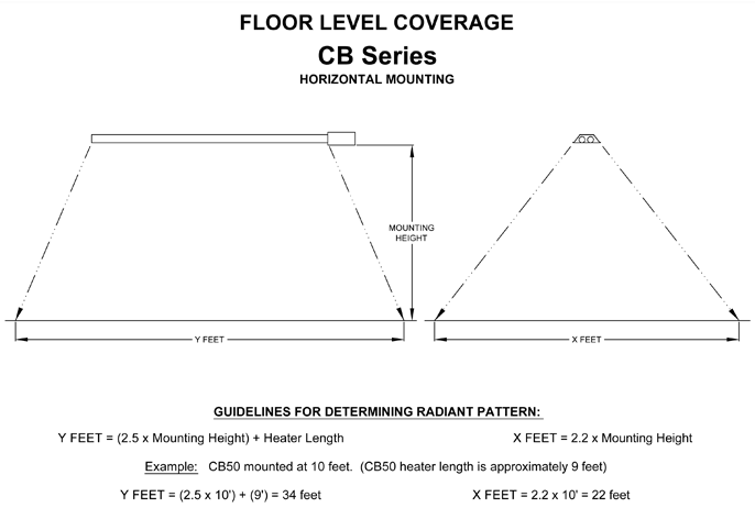
Floor Level Coverage – The above chart may be used as a guideline for primary radiation, i.e. the infrared pattern directly below the heater. In a well-insulated building, only 50% of the floor needs to be covered by the primary radiant pattern. Please be aware that the radiant energy generated by infrared heaters is not limited to the primary radiant pattern. There is additional radiant energy that is absorbed outside the primary area, a secondary radiant pattern. Since concrete is a very good conductor of heat, a reasonably uniform floor temperature eventually will be reached. The amount of time it takes to reach “thermal equilibrium” is in direct correlation to the distance between the heaters.
Learn More >>
Pull-Through System (negative pressure or vacuum)
- Pull-through system — the products of combustion are pulled through the combustion chamber for increased radiant efficiency and greater safety
- CSA certified for vertical or horizontal venting
- CSA certified for maximum 75 ft. horizontal sidewall venting
- 4″ O.D. flue connection
- Draft inducer is equipped with permanently lubricated, totally enclosed, fan cooled and heavy duty ball bearing motor for maintenance free operation
- Draft inducer assembly can be used for through- the-roof-venting or rotated 45 degrees or 90 degrees for horizontal venting
Burner System
- One piece cast iron burner
- 10 year limited warranty on burner
- Inside or optional outside air for combustion
- CSA certified for 50 ft. outside combustion air inlet duct
- 4″ O.D. standard combustion fresh air inlet duct opening
- Burner inspection sight glass
- State-of-the-art step opening combination gas valve for quiet ignition
- Diaphragm Air Proving Switch — a safety device for proof of venting before gas flow and ignition
- Spark ignition system with 100% Gas Shut-Off Safety Control (30 second pre-purge)
- 36″ Stainless Steel flexible gas connector included with control box
Radiant Emitter Tube System
- All radiant emitter tubes are 3″ O.D
- Aluminized steel emitter tubes are calorized for long life and high radiant efficiency — will not flake or peel, and are corrosion resistant
- The calorization process (PDF) produces an emitter tube which is highly radiant absorptive on the interior and highly radiant emissive on the exterior
- 5 year limited warranty on the emitter tubes
Reflector System
- Fully factory pre-assembled on tube body to minimize field assembly and save installation labor cost
- Highly efficient aluminum reflectors with reflectivity rating of 97%
- Reflector ends are enclosed for maximum radiant heat output and minimum convection loss
- Easy to use mounting brackets
- Suitable for horizontal or angle mount up to 45 degrees
Other
- 3 Monitoring light system for on line diagnosis- power on, insufficient air flow, and ignition sytem operation
- Uncomplicated maintenance access
- Quick slip-on electrical connectors
- 1/2″ MPT gas inlet connection
- CSA approved for indirect vented operation- commercial installations only
- Optional deflector kit for reduced clearances to combustible materials
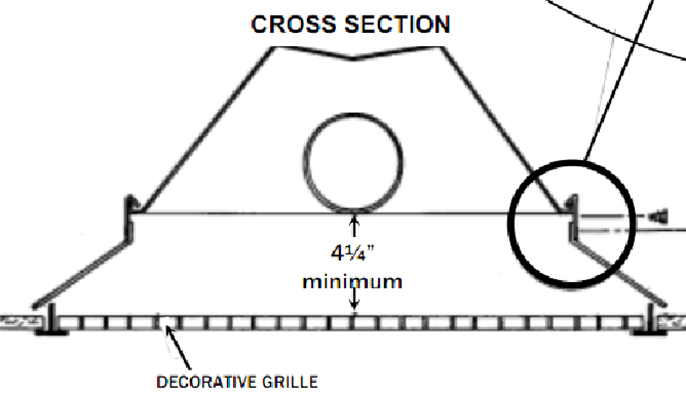
- Optional decorative grille kit for drop ceiling applications
- Optional side reflector kits
- CSA Certified according to ANSI Z83.20 and CSA 2.34. Certified for Residential and Commecial Use
| MODEL | INPUT BTU/HR | TOTAL TUBE LENGTH | OVERALL DIMENSION | SHIPPING WEIGHT Lbs.** |
| CB 20 | 20,000 | 15′ | 9’3″ | 88 |
| CB 30 | 30,000 | 15′ | 9’3″ | 88 |
| CB 40 | 40,000 | 15′ | 9’3″ | 88 |
| CB 50 | 50,000 | 15′ | 9’3″ | 88 |
|
** Hanging weight is 80% of shipping weight
|
||||
| GAS TYPE | BURNER PRESSURE | MINIMUM SUPPLY PRESSURE |
MAXIMUM SUPPLY PRESSURE |
VOLTAGE | AMPS | IGNITION TYPE |
| NATURAL | 3.5″W.C. | 5″W.C. | 14″W.C. | 120VAC | 2.6 | DIRECTSPARK |
| PROPANE | 10″W.C. | 11″W.C. | 14″W.C. | 60HZ |
NOTE: For all installations higher than 2000 ft. above sea level please consult the factory regarding recommended derating of heaters.
| MODEL | MOUNTING ANGLE | SIDES FRONT | SIDES REAR | CEILING | BELOW | ENDS |
| CB(50,40) | 0° 45° |
12″ 40″ |
12″ 4″ |
4″ 4″ |
57″ 57″ |
8″ 8″ |
| CB(30,20) | 0° 45° |
8″ 30″ |
8″ 4″ |
4″ 4″ |
41″ 41″ |
8″ 8″ |
NOTE:
- In U.S., the clearances below with deflector are: CB(50,40) – 42″ and CB(30,20) – 33″
- In Canada, the clearances below the heater are: CB(50,40) – 48″ (36″ with deflector) and CB(30,20) – 36″ (27″ with deflector)
- Maintain 30″ side clearance with deflector
VENTING REQUIREMENTS
Heaters can be common vented, vented or indirect vented. A vented installation must be vented outside the building with a flue pipe. An indirect vented installation requires a minimum ventilation flow of 4 CFM per 1000 BTU/hour of total installed heater capacity on natural gas by either gravity or power ventilation (4.18 CFM per 1000 BTU/hour on propane).
INSTALLATION REQUIREMENTS
Installation and service must be performed by a licensed contractor. The installation must conform to written Instalation & Operating Instructions and local codes. In the absence of local codes, the installation must conform with the National Fuel Gas code, ANSI Z223.1 (latest edition also known as NFPA54) or GCA B149 (latest edition) installation codes. These codes are available from the National Fire Protection Association, Inc., Batterymarch Park, Quincy, MA 02269 or the Canadian Gas Association, 55 Scarsdale Road, Toronto, Ontario M3B 2R3, CANADA.
FOR YOUR SAFETY
Operate infrared heaters with proper care and observe all safety precautions. Carefully follow printed installation, operating and cleaning instructions furnished with the heater. Do not store gasoline or combustible products in the vicinity of the heater. Do not touch the heater or the tubes while the heater is in operation. Adequate ventilation must always be provided in accordance with codes.
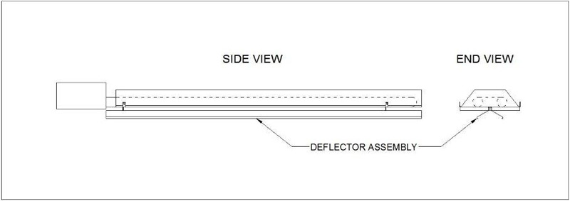
Deflector Kit
The Deflector Kit (Part # 43504000) is used to reduce clearances to combustibles below the heater. It is designed to be used when the CB series is installed in a horizontal position. Details on Deflector Kit (PDF)
Lower Mounting Kit
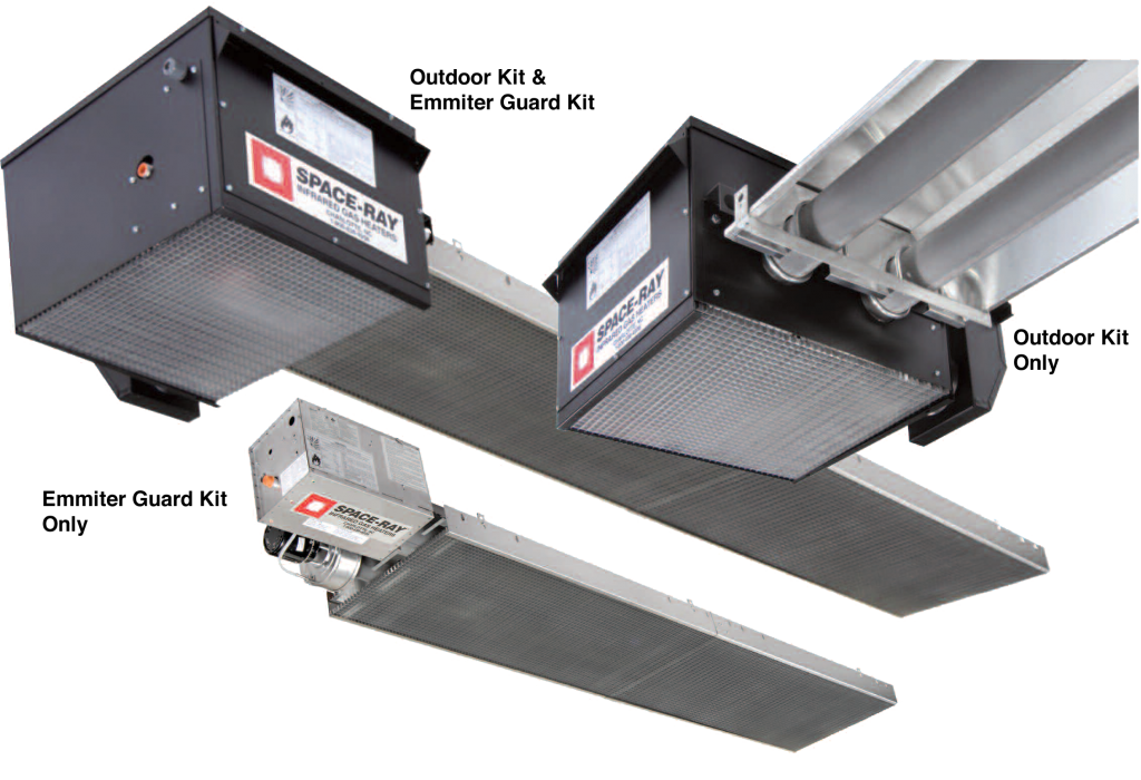
The Lower Mounting Kit (Part #43515000) is required when the CB series of infrared tube heaters is installed at mounting heights between 6 ft. and 8 ft. above a finished floor. The Lower Mounting Kit consists of both the Emitter Guard Kit and the Draft Inducer Guard Kit as described below.
Emitter Guard Kit
The Emitter Guard Kit (Part #43485000) includes an aluminum decorative grille with side emitter guard holder panels. This item and the Draft Inducer Guard Kit make up the Lower Mounting Kit, which must be used in installations with mounting heights between 6 ft. and 8 ft. This item could be used separately in installations above 8 ft., however, for decorative purposes if desired. Details on Emitter Guard Kit (PDF)
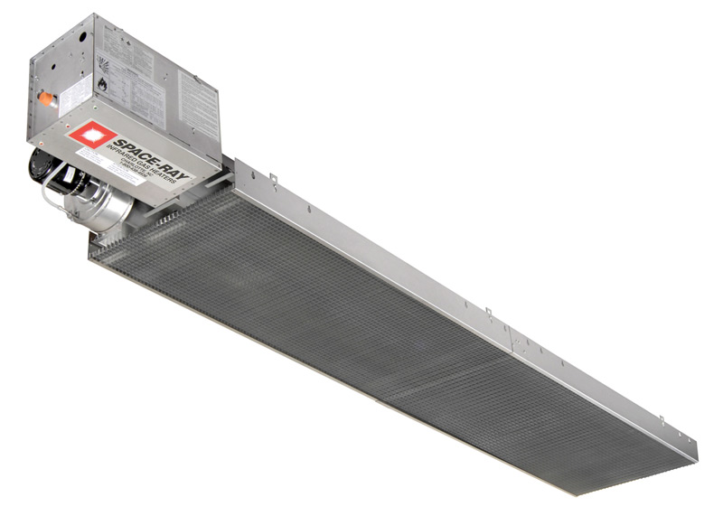
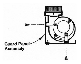
Draft Inducer Guard Kit
The Draft Inducer Guard Kit (Part #43486000) is an aluminum shield mounted around the draft inducer (brackets and screws included).
This item and the Emitter Guard Kit make up the Lower Mounting Kit, which must be used in installations with mounting heights between 6 ft. and 8 ft. Details on Draft Inducer Kit (PDF)
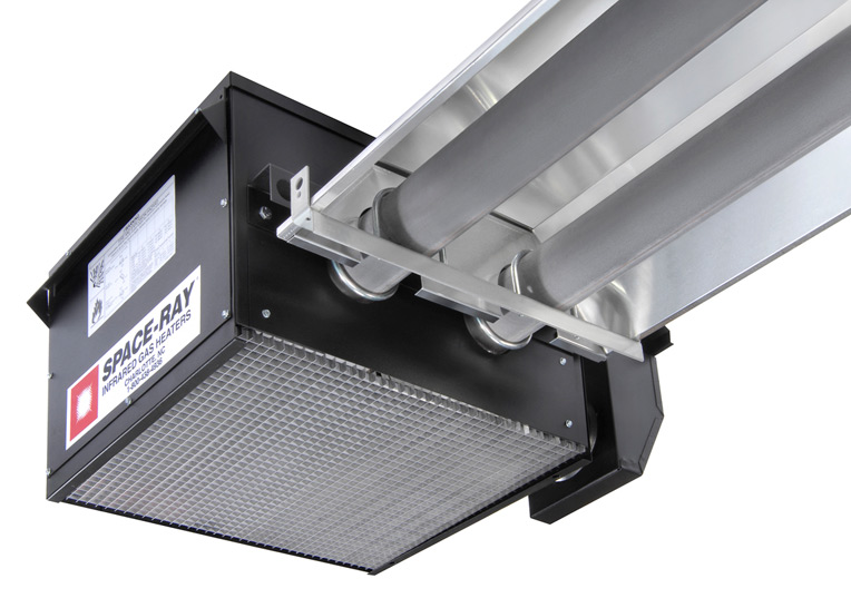
Outdoor Cover Kit
Outdoor Cover Kit (Part # 44444000) protects the burner assembly from inclement weather like rain and snow when the heater is installed outdoor. Outdoor cover kit is not requiredwhen installed in Covered Patio Applications. If desired, the Outdoor Cover Kit can be installed to improve the cosmetic appearance in conjunction with the Emitter Guard Kit. The Emitter Guard Kit improves the aesthetics and diffuses the radiant energy below the heater (the use of the egg crate decorative grille limits the radiant throw of the heater when compared to exposed emitter tubes by approximately 30%). Details on Outdoor Cover Kit Assembly Instructions (PDF)
Remote Control Kit – Part #44640050

Decorative Grille Kits
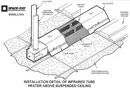
The heaters can be installed over non-combustible suspended ceilings with the use of aluminum decorative grilles.Decorative Grille Installation Instructions (PDF)
Tube Heater Accessories
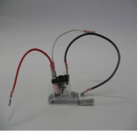
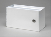
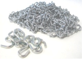
Accessories for common tube heater installations include vent caps, combustion air termination caps, thermostats, programmable digital thermostats, 24V Thermostats relay kits, Thermostat enclosure, Chain Kits, Second Stage Line Regulators, and manual cutoff valves. To learn more click Tube Heater Accessories (PDF).
Troubleshooting
Troubleshooting Flowcharts are located toward the end of each products I & O pdf.




 It has two 150-ton electric furnaces and two continuous casters. There are also rail, bar, rod, wire, seamless tube and other mills, a casting foundry and various auxiliary operations.

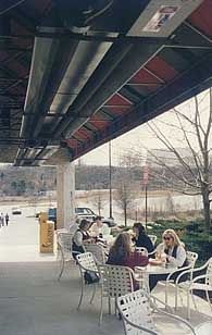 Now when it's cool outside and the heaters are on, often times we fill up the patio before the inside area which seats 75," he said. "Customers are amazed at how warm they are under the heaters when it's 30° Fahrenheit outside