| MODEL | SINGLE STAGE | TWO STAGE | TOTAL EMITTER LENGTH | MINIMUM MOUNTING HEIGHT |
||||
| BTU/HR INPUT | BTU/HR HIGH INPUT | BTU/HR LOW INPUT | VENTED | UNVENTED | ||||
| 20 FT | 30 FT | 20 FT | 30 FT | |||||
| PGR 40 | 40,000 | 40,000 | 25,000 | ● | ● | ● | 10 FT | |
| PGR 50 | 50,000 | 50,000 | 30,000 | ● | ● | ● | ● | 10 FT |
| PGR 60 | 60,000 | 60,000 | 40,000 | ● | ● | ● | ● | 11 FT |
| PGR 75 | 75,000 | 75,000 | 50,000 | ● | ● | ● | 13 FT | |
| PGR 80 | 80,000 | 80,000 | 55,000 | ● | ● | 13 FT | ||
| PGR 100 | 100,000 | 100,000 | 65,000 | ● | ● | 14 FT | ||
| PGR 125 | 125,000 | 125,000 | 80,000 | ● | 14 FT | |||
Indicate model number based on Btu/hr input (e.g., 100,000 Btu/hr), total emitter length, (e.g., 30 feet) and gas type (e.g., natural gas single stage input). The unit selection for a straight tube
would be PGR100-30-N5, *MOUNT HEATERS AS HIGH AS POSSIBLE. Minimums are shown for indoor applications as a guideline for human comfort and uniform energy distribution.
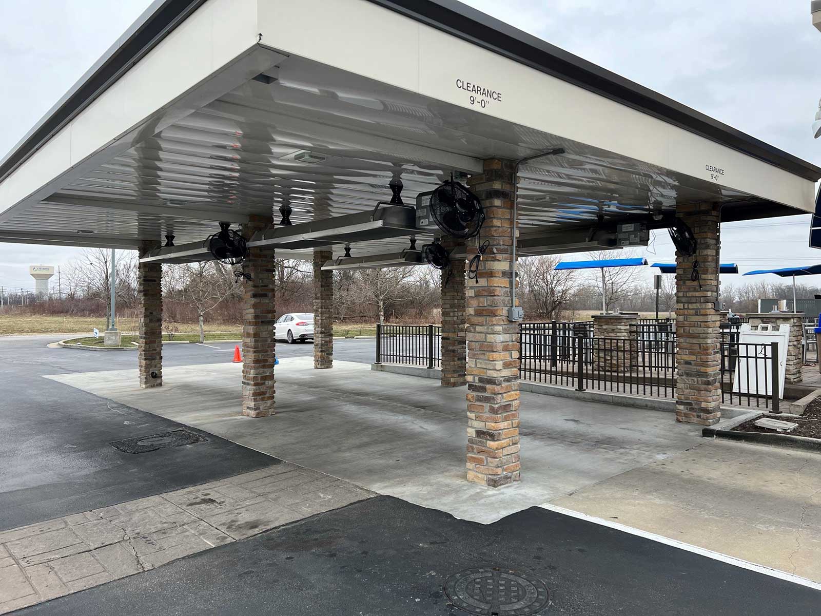
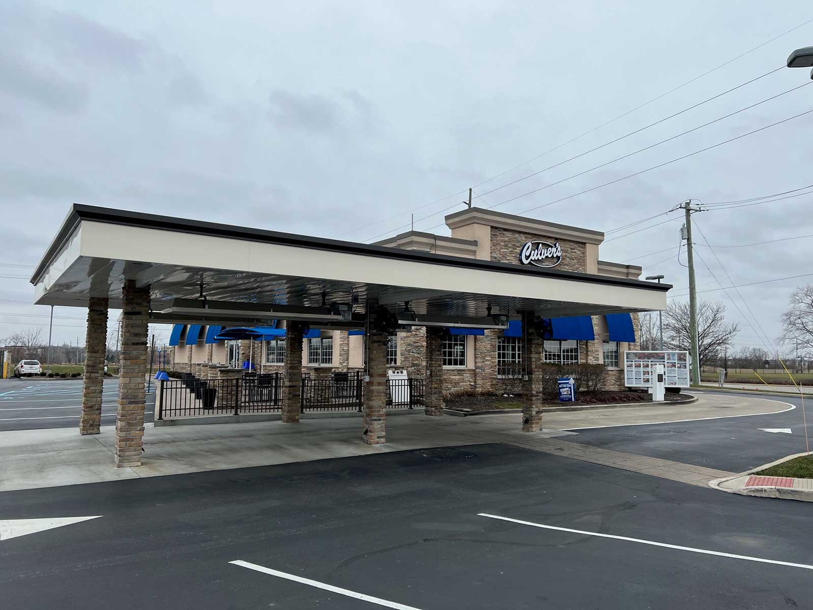
For outdoor applications heaters can be mounted lower. Consult your Space-Ray representative for the particulars of your installation requirements.
| Control Suffix | Type of Gas | Control Option Description | |||||
| N5/ L5 | Natural / Propane | Single Stage Gas Valve- Single Stage Input | |||||
| N7 / L7 | Natural / Propane | Two Stage Gas Valve- Modulating Input – High/Low Fire | |||||
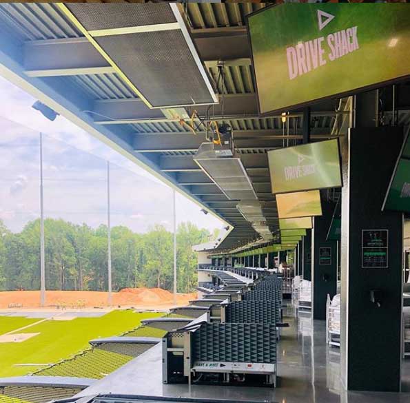
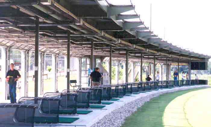
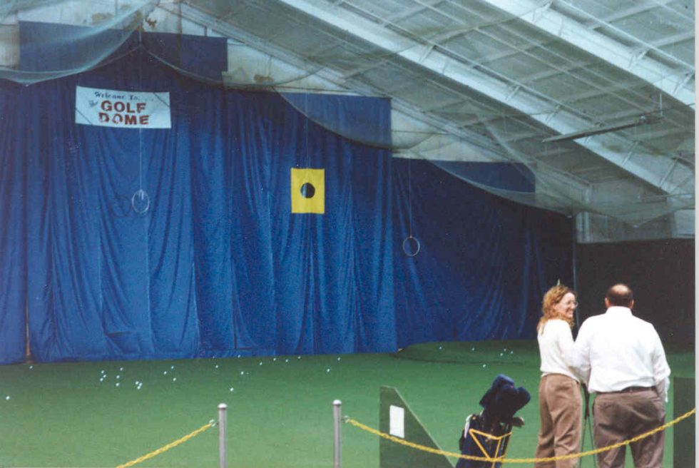
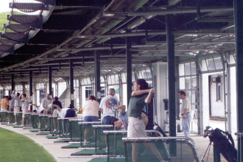
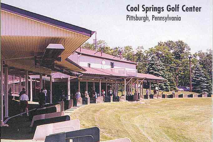
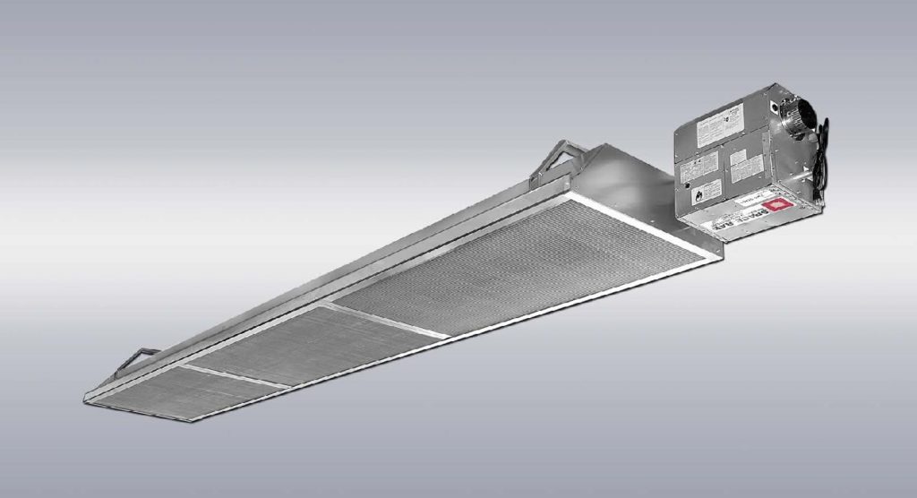
PGR Series is Specifically designed for Golf Range Applications
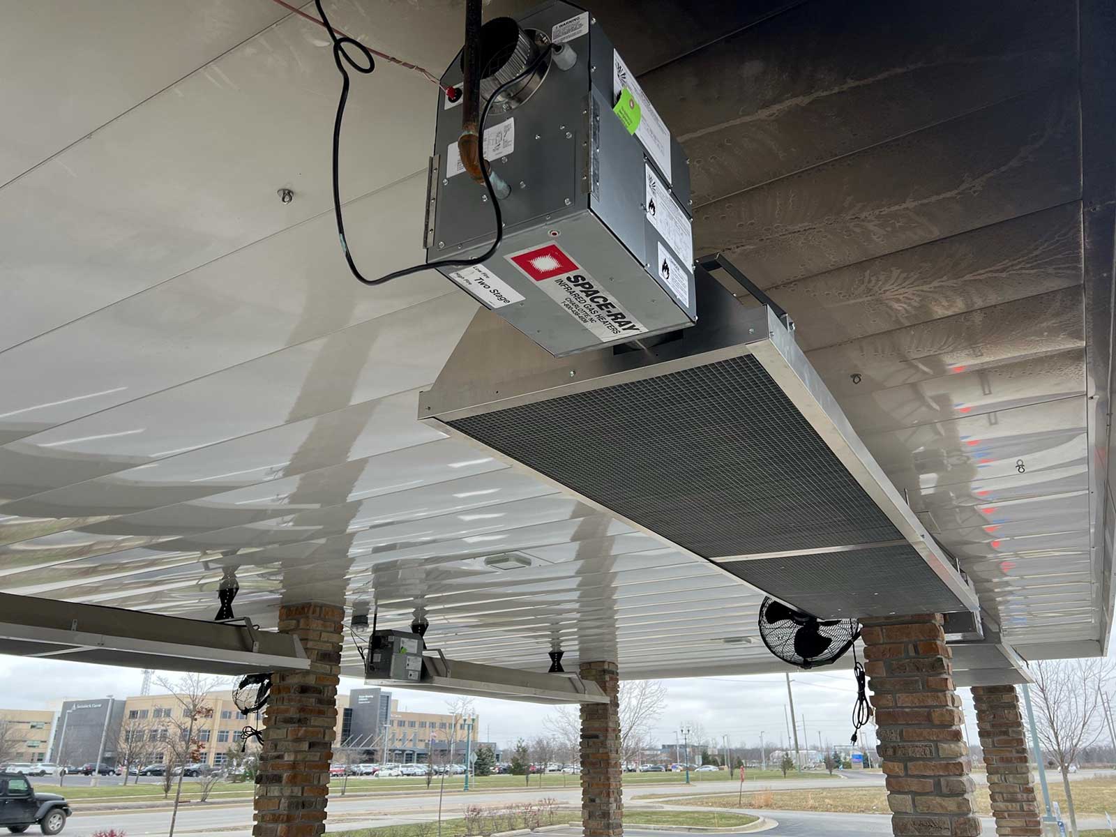
- Emitter Tubes are all calorized steel for higher radiant efficiency and corrosion resistance
- Emitter tube terminates inside the reflector body and the products of combustion is
discharged under the reflector body to increase the return tube temperature and
improve overall efficiency - No exposed exhauster motors. The blower is enclosed inside the burner box for quieter
system operation and less maintenance. - Two Point Tube Suspension System with the External Frame Brackets to minimize
assembly & installation time. - Vented application requires Vent Kit (Part# 44622000).
Push Through System (positive pressure)
- Products of combustion are pushed through the combustion chamber.
- No draft hoods, totally enclosed combustion chamber.
- Blower motor totally enclosed in the burner box, ideal for applications where minimal noise (less than 50dB) is desired.
Burner System
- Heavy duty cast iron burner
- 10- year limited warranty on burner
- Inside or optional outside air for combustion
- Up to 40 ft. outside combustion air duct capability
- Standard 4″ combustion air collar
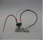
- Reliable direct spark ignition system and 100% gas shut-off safety control
- Pre-purge and post-purge function
- State-of-the-art step opening redundant combination gas valve for quiet ignition and added safety
- Diaphragm air switch for proof of venting before gas flow and ignition
- Diagnostic monitoring light system
- Burner inspection sight glass
- Line voltage or external 24V thermostat connection
- 36″ stainless steel flexible gas connector included with burner box
| GAS TYPE | BURNER PRESSURE | SUPPLY PRESSURE | GAS CONNECTION | VOLTAGE | AMPS | IGNITION TYPE | FLUE CONNECTION | OUTSIDE COMBUSTION AIR CONNECTION |
|
| MIN | MAX | ||||||||
| NATURAL | 3.5″W.C. | 5″W.C. | 14″W.C. | 1/2″ MPT | 120 VAC 60 HZ |
1.8 | DIRECT SPARK | 4″ ROUND | 4″ ROUND |
| PROPANE | 10″ W.C. | 11″W.C. | 14″W.C. | ||||||
NOTE: For all installations higher than 2000 ft. above sea level please consult the factory regarding recommended derating of heaters.
![]()
| MODEL | MOUNTED HORIZONTALLY | |||
| SIDES | CEILING* | BELOW | ENDS | |
| PGR 40, 50 | 22″ | 8″ | 66″ | 15″ |
| PGR 60, 75, 80 | 22″ | 8″ | 70″ | 15″ |
| PGR 100 | 28″ | 8″ | 80″ | 15″ |
| PGR 125 | 28″ | 10″ | 86″ | 20″ |
*indicates clearances in unvented applications.
▲WARNING: Certain materials or objects, when stored under the heater, will be subjected to radiant heat and
could be seriously damaged. Observe the Minimum Clearances to Combustibles listed in the manual and on the
heater at all times.
COMBUSTION AIR AND VENTILATION
Combustion air and venting requirements for all gas-fired heating equipment must be provided per the National Fuel Gas Code NFPA54 or the authority having jurisdiction Heaters can be vented, indirect vented or unvented. Refer to the Installation and Operation Instructions for further information. A vented installation must be vented to the outside of the building with a flue pipe. In indoor and tightly sealed buildings this heater requires ventilation. An Indirect vented installation requires a minimum ventilation flow of 4 CFM per 1000 Btu/hr of total installed heater capacity on natural gas by either gravity or power ventilation,
INSTALLATION REQUIREMENTS
Installation and service must be performed by a licensed contractor. The installation must conform to written Instalation & Operating Instructions and local codes. In the absence of local codes, the installation must conform with the National Fuel Gas code, ANSI Z223.1 (latest edition also known as NFPA54) or GCA B149 (latest edition) installation codes. These codes are available from the National Fire Protection Association, Inc., Batterymarch Park, Quincy, MA 02269 or the Canadian Gas Association, 55 Scarsdale Road, Toronto, Ontario M3B 2R3, CANADA.
FOR YOUR SAFETY
Operate infrared heaters with proper care and observe all safety precautions. Carefully follow printed installation, operating and cleaning instructions furnished with the heater. Do not store gasoline or combustible products in the vicinity of the heater. Do not touch the heater or the tubes while the heater is in operation. Adequate ventilation must always be provided in accordance with codes.
The stated clearance to combustibles represents a surface temperature of 90 ºF (32 ºC) above room
temperature. Building materials with a low heat tolerance (such as plastics, vinyle siding, canvas, tri-ply, etc.)
may be subject to degradation at lower temperatures. It is the installer’s responsibility to assure that adjacent
materials are protected from degradation.
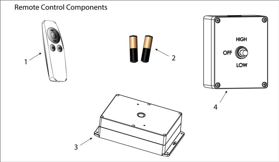
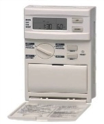
Remote Control Kit – Part# 44640070
Tube Heater Accessories
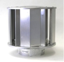
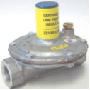
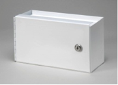
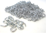
Accessories for common tube heater installations include vent caps, combustion air termination caps, thermostats, programmable digital thermostats, 24V Thermostats relay kits, Thermostat enclosure, Chain Kits, Second Stage Line Regulators, and manual cutoff valves. To learn more click Tube Heater Accessories (PDF).

Troubleshooting
Troubleshooting Flowcharts are located toward the end of each products I & O pdf.