
| MODEL | SINGLE STAGE BTU/HR INPUT | TWO STAGE | MIN MOUNTING HEIGHT |
||||||
| BTU/HR HIGH INPUT | BTU/HR LOW INPUT | ||||||||
| WB35 | 35,000 | 35,000 | 24,000 | 7′ | |||||
| WB50 | 50,000 | 50,000 | 33,000 | 9′ | |||||
* Indicate model number based on Btu/hr input (e.g. 35,000Btu/hr),Control suffix (e.g. Natural Gas two stage input ) . The unit selection would be WB35-N7.
** Minimum recommended heights are intended as a guide only, as heaters may be mounted at various heights and angles. Mount heaters as high as possible. Minimums are shown as a guideline for human comfort and uniform energy distribution for complete building applications. Please consult your Space-Ray Representative for a detailed analysis of your particular heating requirements.
| Control Suffix | Type of Gas | Control Option Description | |||||
| N7 / L7 | Natural / Propane |
Two Stage Gas Valve- Modulating Input – High/Low Fire |
|||||
| N10 / L10 | Natural / Propane |
Two Stage Gas Valve- Modulating Input – High/Low Fire |
|||||
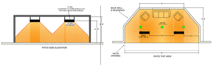
Heater Sizing & Layouts-
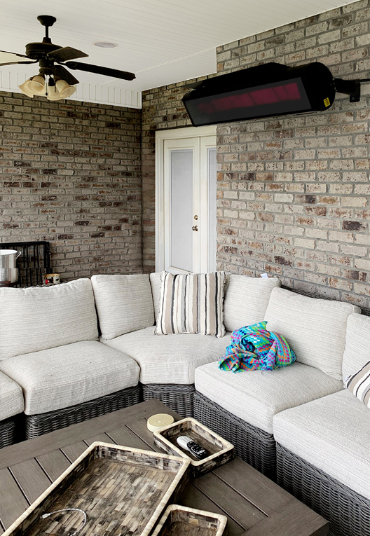
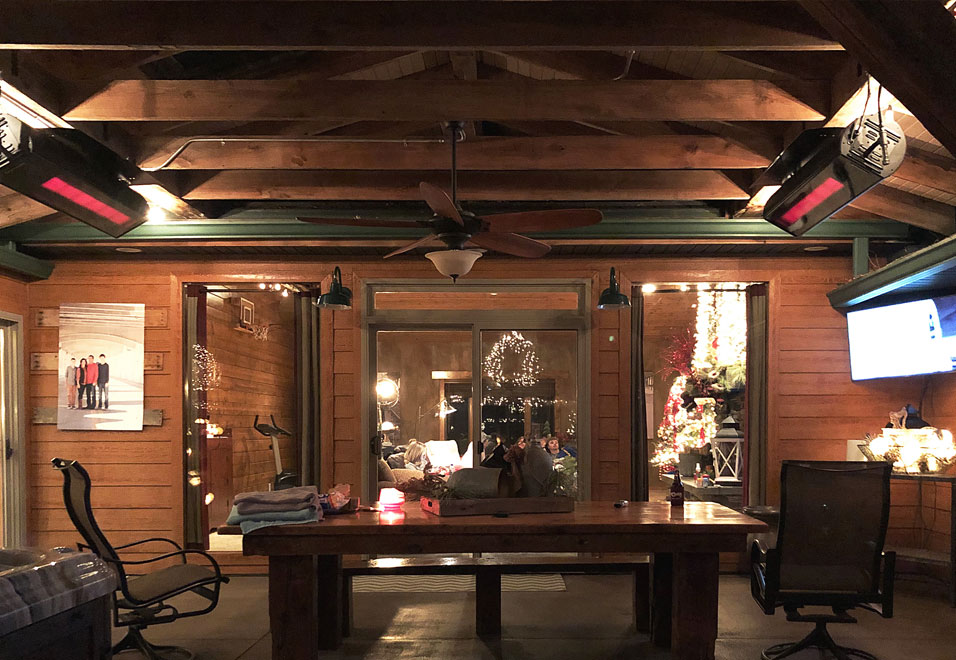
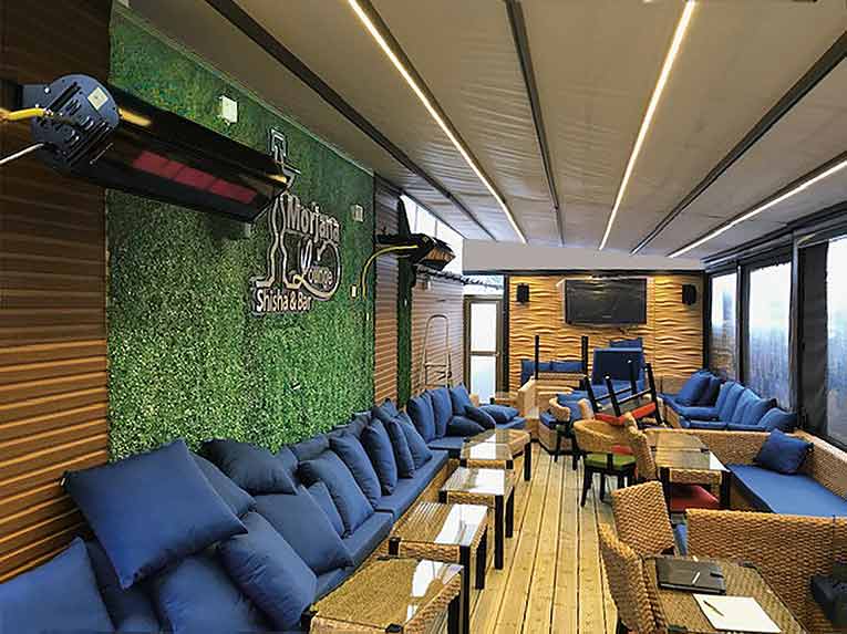
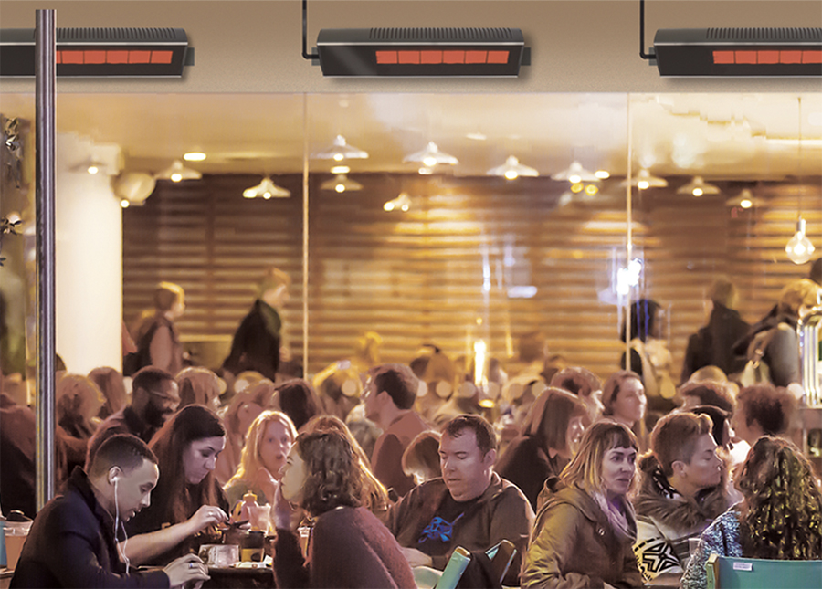
Radiant heaters work like the sun to emit radiant heat directly to the space to increase the comfort of the patio guests. Suitable applications include patios, porches, outdoor shopping areas and pathways.
The amount of temperature increase in outdoor patio spaces will be dependent on the following factors:
- The number of heaters in the space is important to provide good coverage of the area to be heated.
- Take care not to mount the heaters too low or too close together this can make people directly below the heaters uncomfortable.
- It is recommended to use a suitable windbreak to reduce the effects of direct wind on the patio. If an area is going to be unprotected and is a breezy location then heaters may need to located closer together. Wind breaks must be designed to allow fresh air for ventilation.
- Angling the heaters greater than 30 degrees should be avoided unless the mounting height is low, when the heaters are angled more than 30 degrees the radiant intensity is lower and will reduce the amount of heat felt by the guests.
- It is recommended to place the heaters in the area of greatest heat loss facing into the patio area.
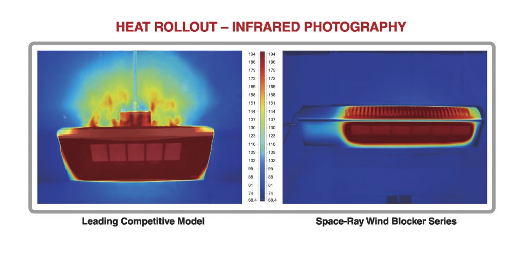
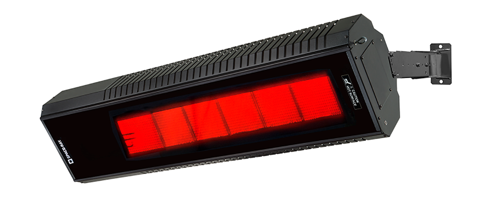
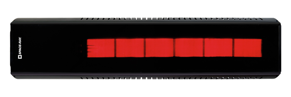
- Indoor or Outdoor Rated. Can be exposed to outdoor elements – rain or snow.
- Tinted ceramic glass technology provides Wind resistance up to 40mph wind force.
- Provides a totally enclosed combustion pattern and maintains consistent output even in windy environments.
- Horizontal or angle mounting up to 60°.
- Clearances as low as 10” above the heater with an optional shield.
- Can be suspended from ceiling or angle mounted from column or sidewall with optional adjustable mounting brackets.
- Factory shipped as a two-stage control heater and can be used with optional 3 position switch for ultimate comfort. Operate at first stage during milder days and operate at full power on colder days.
- Can be operated at full power as a single stage heater by a simple factory supplied jumper wire.
- 3-year limited warranty on the burner assembly, and 1-year limited warranty on the controls.
- CSA Design Certified – ANSI Z83.19 & ANSI Z83.26 Standards.
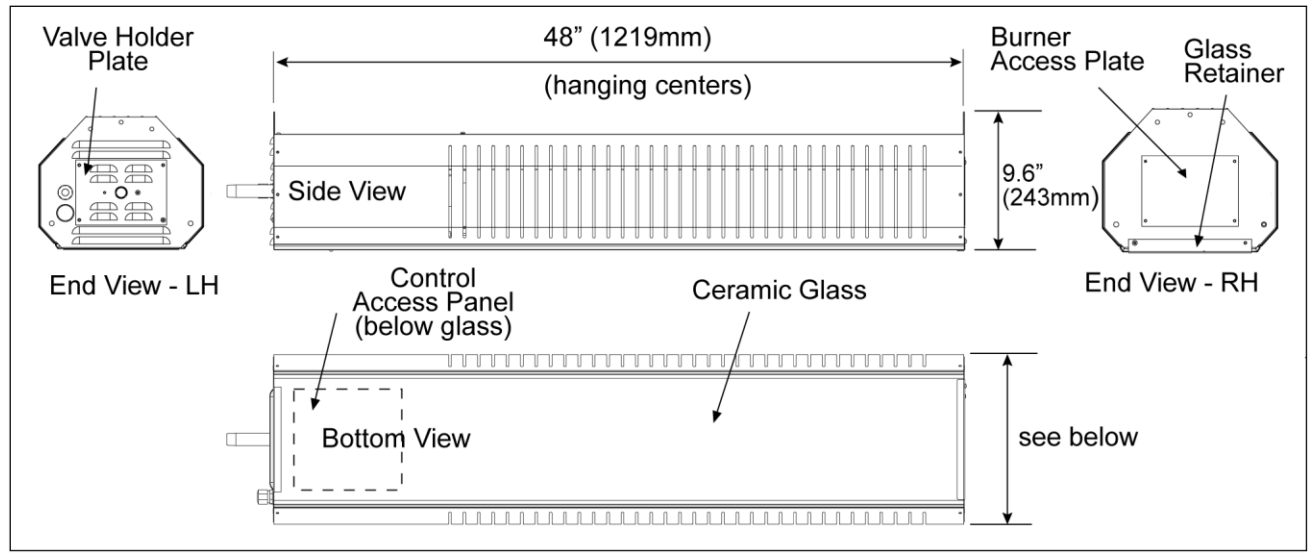
| MODEL | INPUT BTU/HR | HEIGHT | OVERALL DIMENSION | SHIPPING WEIGHT Lbs.** |
| WB 35 | 35,000 | 9.6″ | 48″ | 55 |
| WB 50 | 50,000 | 9.6″ | 48″ | 62 |
|
** Hanging weight is 85% of shipping weight
|
||||
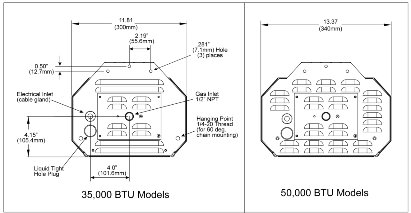
WB35 Dimensions
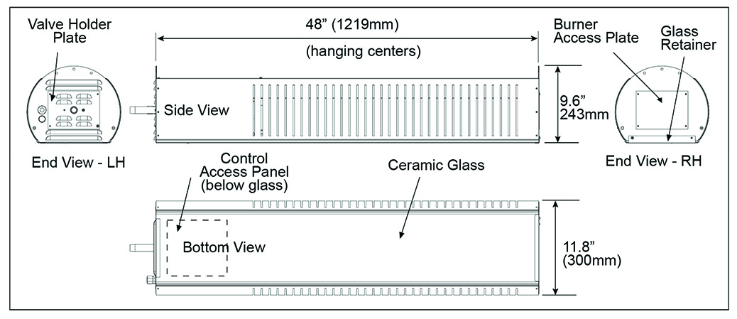
WB50 Dimensions
| GAS TYPE | BURNER PRESSURE | MINIMUM SUPPLY PRESSURE |
MAXIMUM SUPPLY PRESSURE |
VOLTAGE | AMPS | IGNITION TYPE |
| NATURAL | 6″W.C. | 7″W.C. | 14″W.C. | 120VAC | 0.4 | DIRECT SPARK |
| PROPANE | 11″W.C. | 11.5″W.C. | 14″W.C. | 60HZ |
![]() The stated clearance to combustibles represents a surface temperature of 117º F (65º C) above room temperature. Building materials with a low heat tolerance (such as plastics, vinyl siding, canvas, tri-ply, etc.) may be subject to degradation at lower temperatures. It is the installer’s responsibility to assure that adjacent materials are protected from degradation.
The stated clearance to combustibles represents a surface temperature of 117º F (65º C) above room temperature. Building materials with a low heat tolerance (such as plastics, vinyl siding, canvas, tri-ply, etc.) may be subject to degradation at lower temperatures. It is the installer’s responsibility to assure that adjacent materials are protected from degradation.
See below the possible surface temperature at the clearance to combustible distance for different ambient temperatures within the heated space.
| AMBIENT TEMPERATURE | 70°F (21.1°C) | 65°F (18.3°C) | 60°F (15.5°C) |
| SURFACE TEMPERATURE | 187°F (86.1°C) | 182°F (83.3°C) | 177°F (80.6°C) |
This heater is approved for both INDOOR and OUTDOOR installation. Both installation options have different clearances to combustibles as described below. These must be observed.
INDOOR clearances to combustibles are defined as a surface temperature of 90°F above ambient temperature.
OUTDOOR clearances to combustibles are defined as a surface temperature of 117°F above ambient temperature.
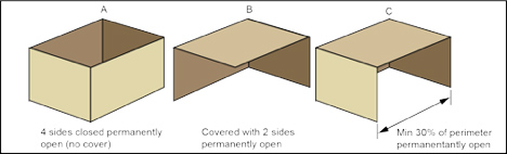
OUTDOOR Spaces are defined as a shelter no more inclusive than:
a) With walls on all sides, but with no overhead cover
b) Within a partial enclosure which includes an overhead cover and no more than two side walls. These side walls may be parallel, as in a breezeway, or at right angles to each other
c) Within a partial enclosure which includes an overhead cover and three side walls, as long as 30 percent or more of the horizontal periphery of the enclosure is permanently open.
Minimum clearances shall be measured from the outer surfaces of the heater or heat shield if installed, as shown in the diagrams for the different installation positions.
 Fire sprinkler heads must be located at an appropriate distance from the heater. This distance may exceed the published clearance to combustibles. Certain applications will require the use of high-temperature sprinkler heads or relocation of the heaters.
Sprinkler systems containing propylene glycol or other flammable substances are not to be used in conjunction with this heater without careful consideration for and avoidance of potential fire or explosion hazards. For further information consult the authority having jurisdiction. Always observe applicable state and local codes.
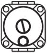
Always maintain minimum clearances and post signs where needed. This heater is supplied with a wall mounted sign shown below. It is the installers responsibility to ensure that the sign is completed with the correct clearance to combustible distances for the installation and that the sign is posted in a location where it is easily accessed.
The stated clearance to combustibles represents a surface temperature of 117º F (65º C) above room temperature. Building materials with a low heat tolerance (such as plastics, vinyl siding, canvas, tri-ply, etc.) may be subject to degradation at lower temperatures. It is the installer’s responsibility to assure that adjacent materials are protected from degradation.
See below the possible surface temperature at the clearance to combustible distance for different ambient temperatures within the heated space.
| AMBIENT TEMPERATURE | 70°F (21.1°C) | 65°F (18.3°C) | 60°F (15.5°C) |
| SURFACE TEMPERATURE | 187°F (86.1°C) | 182°F (83.3°C) | 177°F (80.6°C) |
This heater is approved for both INDOOR and OUTDOOR installation. Both installation options have different clearances to combustibles as described below. These must be observed.
INDOOR clearances to combustibles are defined as a surface temperature of 90°F above ambient temperature.
OUTDOOR clearances to combustibles are defined as a surface temperature of 117°F above ambient temperature.
OUTDOOR Spaces are defined as a shelter no more inclusive than:
a) With walls on all sides, but with no overhead cover
b) Within a partial enclosure which includes an overhead cover and no more than two side walls. These side walls may be parallel, as in a breezeway, or at right angles to each other
c) Within a partial enclosure which includes an overhead cover and three side walls, as long as 30 percent or more of the horizontal periphery of the enclosure is permanently open.
Minimum clearances shall be measured from the outer surfaces of the heater or heat shield if installed, as shown in the diagrams for the different installation positions.
Fire sprinkler heads must be located at an appropriate distance from the heater. This distance may exceed the published clearance to combustibles. Certain applications will require the use of high-temperature sprinkler heads or relocation of the heaters.
Sprinkler systems containing propylene glycol or other flammable substances are not to be used in conjunction with this heater without careful consideration for and avoidance of potential fire or explosion hazards. For further information consult the authority having jurisdiction. Always observe applicable state and local codes.
Always maintain minimum clearances and post signs where needed. This heater is supplied with a wall mounted sign shown below. It is the installers responsibility to ensure that the sign is completed with the correct clearance to combustible distances for the installation and that the sign is posted in a location where it is easily accessed.
The stated clearance to combustibles represents a surface temperature of 117º F (65º C) above room temperature. Building materials with a low heat tolerance (such as plastics, vinyl siding, canvas, tri-ply, etc.) may be subject to degradation at lower temperatures. It is the installer’s responsibility to assure that adjacent materials are protected from degradation.
See below the possible surface temperature at the clearance to combustible distance for different ambient temperatures within the heated space.
| AMBIENT TEMPERATURE | 70°F (21.1°C) | 65°F (18.3°C) | 60°F (15.5°C) |
| SURFACE TEMPERATURE | 160°F (71.1°C) | 155°F (68.3°C) | 150°F (65.6°C) |
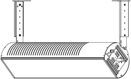
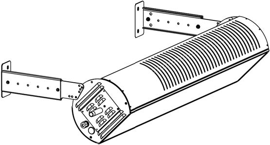
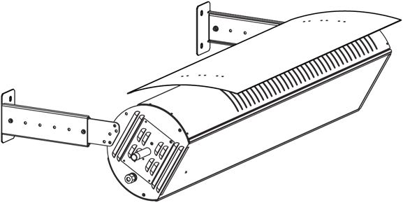
Wall / Ceiling Telescopic (44560352)
Wall / Ceiling Telescopic Mounting Bracket Kit- 15″-30″ overhead space (check clearances to combustibles space above the heater before ordering) includes both the 15-22” and 22-30” extension legs.
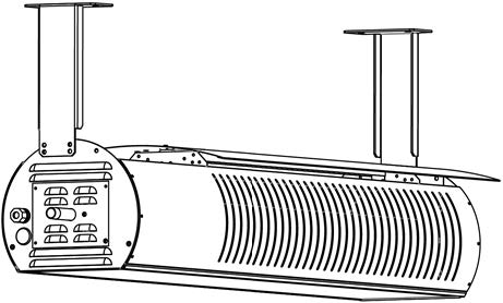
Ceiling Mount Bracket Kit (44560353)
Ceiling Mount Bracket Kit- 10″ fixed installation for minimum overhead clearance. This bracket is only for horizontal mounting with the heat shield.
Heat Shield Kit (44566300 WB35)
Heat Shield Kit – Reduced clearances to combustible option when installed. Mounting angles are restricted to 0, 15, 30, 45 and 60°.
Heat Shield Kit (44566400
WB50 )
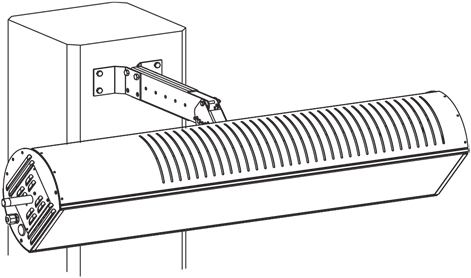
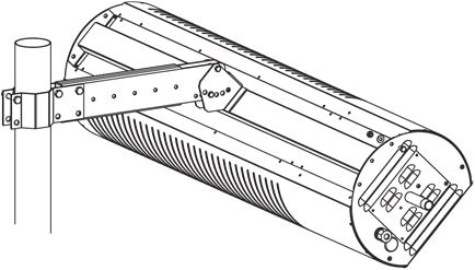
Column Mounting Arm Kit (44560590)
Column Mounting Arm Kit – suitable for columns 8” and wider.
3 ” Pole Mounting Bracket Kit (44560600)
4″ Pole Mounting Bracket Kit (44560609)
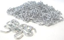
Chain Kit, 12 ft. chain w/ 8 hooks (41690120)
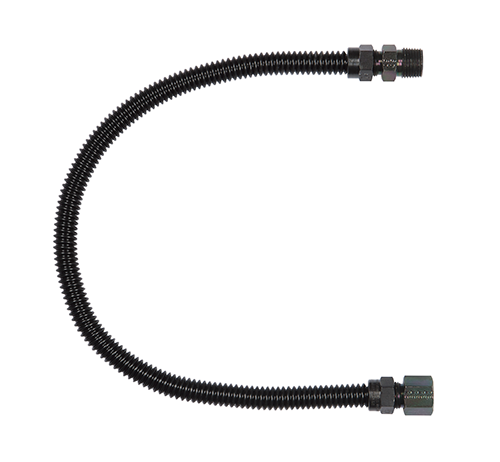
Gas Connector (30302241)
Gas Connector – Black Powder Coated Paint to match the heater. 1/2″OD -24″ Long with 1/2MIP X 1/2 FIP Connection.
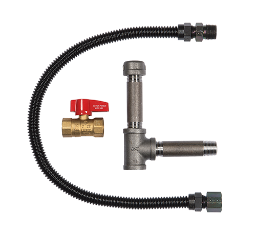
Gas Connection Kit- 1/2″ (44604500)
Gas Connection Kit- 1/2″-Includes Gas Connector, Manual Ball Valve, Sediment Trap (Tee, Cap, Nipple), Thread Sealing Compound.
Gas Regulator (03307260)
Gas regulator 2psig to 11” w.c. ½” NPT inlet and outlet.
3 Position Switch Kit (40147010)
3 Position Switch Kit, (High/Low/Off) for manual heater control (N7/L7).
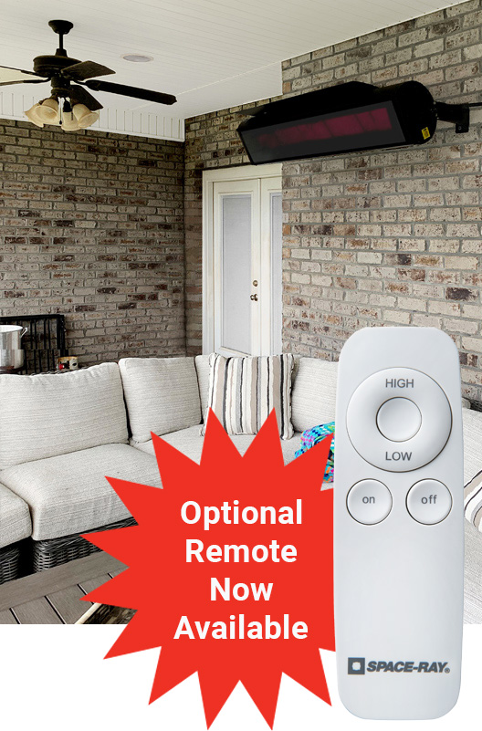
Remote Control (30809990)
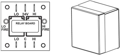
Two Stage Relay Kit (44195000)
Two Stage Relay Kit (one per heater required) for controlling multiple heaters w/a single 24V Two Stage thermostat.