Ordering Information – Single Phase
| MODEL | BTUH | VOLTS | PHASE | Kw | AMPS | STAGE 1 | STAGE 2 | # OF ELEMENTS | INTERNAL CB | MOTOR | MOTOR FLA | SIZE | WT. (lbs) |
|---|---|---|---|---|---|---|---|---|---|---|---|---|---|
| KFS2004-1-ECM | 12,799 | 208 | 1 | 3.8 | 18 | 4 kW | *N/A | 1 | 60 | 1/3HP | 2.9 | Fig. A | 57 |
| KFS2005-1-ECM | 17,065 | 208 | 1 | 5 | 24 | 5 kW | *N/A | 1 | 60 | 1/3HP | 2.9 | Fig. A | 57 |
| KFS2008-1-2S1-ECM | 27,304 | 208 | 1 | 8 | 36 | 4.25 kW | 3.75 kW | 2 | 60 | 1/3HP | 2.9 | Fig. A | 57 |
| KFS2010-1-2S1-ECM | 34,130 | 208 | 1 | 10 | 48 | 5 kW | 5kW | 2 | 60 | 1/3HP | 2.9 | Fig. A | 65 |
| KFS2012-1-2S1-ECM | 40,956 | 208 | 1 | 12 | 58 | 7.5 kW | 4.5 kW | 3 | 60 | 1/3HP | 2.9 | Fig. A | 74 |
| KFS2015-1-2S1-ECM | 51,195 | 208 | 1 | 15 | 72 | 10 kW | 5 kW | 3 | 60+60 | 1/3HP | 2.9 | Fig. A | 74 |
| KFS2020-1-2S1-ECM | 68,260 | 208 | 1 | 20 | 96 | 10 kW | 10kW | 4 | 60+60 | 1/2HP | 2.9 | Fig. B | 76 |
| KFS2025-1-2S1-ECM | 85,325 | 208 | 1 | 25 | 120 | 15 kW | 10 kW | 5 | 60+60+60 | 3/4HP | 2.9 | Fig. B | 81 |
| KFS2030-1-2S1-ECM | 102,390 | 208 | 1 | 30 | 144 | 20 kW | 10 kW | 6 | 60+60+60 | 3/4HP | 2.9 | Fig. B | 85 |
| KFS2404-1-ECM | 13,652 | 240 | 1 | 4 | 17 | 4 kW | *N/A | 1 | 60 | 1/3HP | 2.7 | Fig. A | 57 |
| KFS2405-1-ECM | 17,065 | 240 | 1 | 5 | 21 | 5 kW | *N/A | 1 | 60 | 1/3HP | 2.7 | Fig. A | 57 |
| KFS2408-1-2S1-ECM | 27,304 | 240 | 1 | 8 | 33 | 4 kW | 4 kW | 2 | 60 | 1/3HP | 2.7 | Fig. A | 57 |
| KFS2410-1-2S1-ECM | 34,130 | 240 | 1 | 10 | 42 | 5kW | 5 kW | 2 | 60 | 1/3HP | 2.7 | Fig. A | 65 |
| KFS2412-1-2S1-ECM | 40,956 | 240 | 1 | 12 | 50 | 5.75 kW | 5.75 kW | 2 | 60 | 1/3HP | 2.7 | Fig. A | 74 |
| KFS2415-1-2S1-ECM | 51,195 | 240 | 1 | 15 | 63 | 10 kw | 5 kW | 3 | 60+60 | 1/3HP | 2.7 | Fig. A | 74 |
| KFS2418-1-2S1-ECM | 58,874 | 240 | 1 | 17.3 | 72 | 11.5 kw | 5.75 kW | 3 | 60+60 | 1/3HP | 2.7 | Fig. A | 74 |
| KFS2420-1-2S1-ECM | 68,260 | 240 | 1 | 20 | 83 | 10kw | 10 kW | 4 | 60+60 | 1/2HP | 3.9 | Fig. B | 76 |
| KFS2425-1-2S1-ECM | 85,325 | 240 | 1 | 25 | 104 | 15 kW | 10 kW | 5 | 60+60+60 | 1/2HP | 3.9 | Fig. B | 81 |
| KFS2430-1-2S1-ECM | 102,390 | 240 | 1 | 30 | 125 | 20 kW | 10 kW | 6 | 60+60+60 | 3/4HP | 3.9 | Fig. B | 85 |
| KFS2435-1-2S1-ECM | 117,749 | 240 | 1 | 34.5 | 144 | 23 kW | 11.5 kW | 6 | 60+60+60 | 3/4HP | 3.9 | Fig. B | 85 |
| KF4804-1-ECM | 13,652 | 480 | 1 | 4 | 8 | 4 kW | *N/A | 1 | NO | 1/3HP | 0.7 | Fig. A | 57 |
| KF4805-1-ECM | 17,065 | 480 | 1 | 5 | 10 | 5 kW | *N/A | 1 | NO | 1/3HP | 0.7 | Fig. A | 57 |
| KF4808-1-2S1-ECM | 27,304 | 480 | 1 | 8 | 17 | 4 kW | 4 kW | 2 | NO | 1/3HP | 0.7 | Fig. A | 57 |
| KF4810-1-2S1-ECM | 34,130 | 480 | 1 | 10 | 21 | 5 kW | 5 kW | 2 | NO | 1/3HP | 0.7 | Fig. A | 65 |
| KF4812-1-2S1-ECM | 40,956 | 480 | 1 | 12 | 25 | 8 kW | 4 kW | 3 | NO | 1/3HP | 0.7 | Fig. A | 74 |
| KF4815-1-2S1-ECM | 51,195 | 480 | 1 | 15 | 31 | 10 kW | 5 kW | 3 | NO | 1/3HP | 0.7 | Fig. A | 74 |
| KF4818-1-2S1-ECM | 58,874 | 480 | 1 | 17.3 | 36 | 11.5 kW | 5.75 kW | 3 | NO | 1/3HP | 0.7 | Fig. A | 74 |
| KF4820-1-2S1-ECM | 68,260 | 480 | 1 | 20 | 42 | 15 kW | 5 kW | 4 | NO | 1/2HP | 1.1 | Fig. B | 76 |
| KF4825-1-2S1-ECM | 85,325 | 480 | 1 | 25 | 52 | 15 kW | 10 kW | 5 | NO | 1/2HP | 1.1 | Fig. B | 81 |
| KF4830-1-2S1-ECM | 102,390 | 480 | 1 | 30 | 63 | 20 kW | 10 kW | 6 | NO | 3/4HP | 1.1 | Fig. B | 85 |
| KF4835-1-2S1-ECM | 117,749 | 480 | 1 | 34.5 | 72 | 23 kW | 11.5 kW | 6 | NO | 3/4HP | 1.1 | Fig. B | 85 |
Ordering Information – Three Phase
| MODEL | KW | BTUH | PHASE | VOLTS | AMPS | STAGE 1 | STAGE 2 | ELEMENTS | **THERMOSTAT CONTROL VOLTAGE | MOTOR HP | CFM RANGE | TEMP. RISE RANGE (F) | EFFECTIVE AIR THROW | *SIZE | WT. (lbs.) |
|---|---|---|---|---|---|---|---|---|---|---|---|---|---|---|---|
| KFUH2005-3-ECM | 5 | 17,065 | 3 | 208 | 13.9 | 5 kW | N/A | 1 | 24 | 1/3HP | 708 - 1536 | 18-Aug | 75ft. | Fig. A | 57 |
| KFUH2008-3-2S3-ECM | 8 | 27,304 | 3 | 208 | 20.8 | 4 kW | 4 kW | 2 | 24 | 1/3HP | 708 - 1536 | 18-Aug | 75ft. | Fig. A | 57 |
| KFUH2010-3-2S3-ECM | 10 | 34,130 | 3 | 208 | 27.7 | 5 kW | 5 kW | 2 | 24 | 1/3HP | 708 - 1536 | 18-Aug | 75ft. | Fig. A | 65 |
| KFUH2012-3-2S3-ECM | 12.4 | 42,253 | 3 | 208 | 34.4 | 7.5 kW | 3.75 kW | 3 | 24 | 1/3HP | 708 - 1536 | 18-Aug | 75ft. | Fig. A | 74 |
| KFUH2015-3-2S3-ECM | 15 | 51,195 | 3 | 208 | 41.6 | 10 kW | 5 kW | 3 | 24 | 1/3HP | 708 - 1536 | 18-Aug | 75ft. | Fig. A | 74 |
| KFUH2020-3-2S3-ECM | 20 | 68,260 | 3 | 208 | 55.5 | 15 kW | 5 kW | 4 | 24 | 1/2 HP | 1258 - 1771 | 36- 50 | 90ft. | Fig. B | 76 |
| KFUH2025-3-2S3-ECM | 25 | 85,325 | 3 | 208 | 69.4 | 15 kW | 10 kW | 5 | 24 | 1/2 HP | 1258 - 1771 | 36- 50 | 90ft. | Fig. B | 81 |
| KFUH2030-3-2S3-ECM | 30 | 102,390 | 3 | 208 | 83.3 | 20 kW | 10 kW | 6 | 24 | 3/4 HP | 1592 - 2142 | 44 - 60 | 110ft. | Fig. B | 85 |
| KFUH2040-3-2S3-ECM | 40 | 136,520 | 3 | 208 | 111 | 20kW | 20 kW | 8 | 24 | 2 x 1/2 HP | 2516 - 3542 | 36- 50 | 90ft. | Fig. C | 152 |
| KFUH2050-3-2S3-ECM | 50 | 170,650 | 3 | 208 | 138.8 | 25 kW | 25 kW | 10 | 24 | 2 x 1/2 HP | 2516 - 3542 | 36- 50 | 90ft. | Fig. C | 162 |
| KFUH2060-3-2S3-ECM | 60 | 204,780 | 3 | 208 | 166.5 | 30 KW | 30 kW | 12 | 24 | 2 x 3/4 HP | 3184 - 4284 | 44 - 60 | 110ft. | Fig. C | 170 |
| KFUH2405-3-ECM | 5 | 17,065 | 3 | 240/208* | 12 / 10.4* | 5 kW | *N/A | 1 | 24 | 1/3HP | 1258 - 1771 | 36- 50 | 90ft. | Fig. A | 57 |
| KFUH2410-3-2S3-ECM | 10 | 34,130 | 3 | 240/208* | 24 / 20.8* | 5 kW | 5 kW | 2 | 24 | 1/3HP | 1258 - 1771 | 36- 50 | 90ft. | Fig. A | 65 |
| KFUH2412-3-2S3-ECM | 12 | 40,956 | 3 | 240/208* | 28.9 / 25* | 6 kW | 6 kW | 3 | 24 | 1/3HP | 1258 - 1771 | 36- 50 | 90ft. | Fig. A | 74 |
| KFUH2415-3-2S3-ECM | 15 | 51,195 | 3 | 240/208* | 36.1 / 31.2* | 10 kW | 5 kW | 3 | 24 | 1/3HP | 1258 - 1771 | 36- 50 | 90ft. | Fig. A | 74 |
| KFUH2418-3-ECM | 17.3 | 58,874 | 3 | 240/208* | 41.6 / 36* | 17.25 kW | *N/A | 3 | 24 | 1/3HP | 1258 - 1771 | 36- 50 | 90ft. | Fig. A | 74 |
| KFUH2420-3-2S3-ECM | 20 | 68,260 | 3 | 240/208* | 48.1 / 41.6* | 10 kW | 10 kW | 4 | 24 | 1/2 HP | 1258 - 1771 | 36- 50 | 90ft. | Fig. B | 76 |
| KFUH2425-3-2S3-ECM | 25 | 85,325 | 3 | 240/208* | 60.1 / 52* | 15 kW | 10 kW | 5 | 24 | 1/2 HP | 1258 - 1771 | 36- 50 | 90ft. | Fig. B | 81 |
| KFUH2430-3-2S3-ECM | 30 | 102,390 | 3 | 240/208* | 72.2 / 62.5* | 20 kW | 10kW | 6 | 24 | 3/4 HP | 1592 - 2142 | 44 - 60 | 110ft. | Fig. B | 85 |
| KFUH2435-3-2S3-ECM | 34.5 | 117,749 | 3 | 240/208* | 83 / 71.8* | 17.25 kW | 17.25 kW | 6 | 24 | 3/4 HP | 1592 - 2142 | 44 - 60 | 110ft. | Fig. B | 85 |
| KFUH2440-3-2S3-ECM | 40 | 136,520 | 3 | 240/208* | 96.2 / 83.3* | 20 kW | 20 kW | 8 | 24 | 2 x 1/2 HP | 2516 - 3542 | 36- 50 | 90ft. | Fig. C | 152 |
| KFUH2450-3-2S3-ECM | 50 | 170,650 | 3 | 240/208* | 120.3 / 104* | 25 kW | 25 kW | 10 | 24 | 2 x 1/2 HP | 2516 - 3542 | 36- 50 | 90ft. | Fig. C | 162 |
| KFUH2460-3-2S3-ECM | 60 | 204,780 | 3 | 240/208* | 144.3 / 124.9* | 30 KW | 30 kW | 12 | 24 | 2 x 3/4 HP | 3184 - 4284 | 44 - 60 | 110ft. | Fig. C | 170 |
| KFUH2470-3-ECM | 70 | 238,910 | 3 | 240/208* | 168.4 / 145.7* | 70 kW | *N/A | 12 | 24 | 2 x 3/4 HP | 3184 - 4284 | 44 - 60 | 110ft. | Fig. C | 170 |
| KFUH4805-3-ECM | 6 | 17,065 | 3 | 480 | 7.2 | 5 kW | *N/A | 1 | 24 | 1/3HP | 1258 - 1771 | 36- 50 | 90ft. | Fig. A | 57 |
| KFUH4810-3-2S3-ECM | 10 | 34,130 | 3 | 480 | 12 | 5 kW | 5 kW | 2 | 24 | 1/3HP | 1258 - 1771 | 36- 50 | 90ft. | Fig. A | 65 |
| KFUH4812-3-ECM | 12 | 40,956 | 3 | 480 | 14.4 | 12 kW | *N/A | 3 | 24 | 1/3HP | 1258 - 1771 | 36- 50 | 90ft. | Fig. A | 74 |
| KFUH4815-3-2S3-ECM | 15 | 51,195 | 3 | 480 | 18 | 10 kW | 5 kW | 3 | 24 | 1/3HP | 1258 - 1771 | 36- 50 | 90ft. | Fig. A | 74 |
| KFUH4818-3-ECM | 18 | 58,874 | 3 | 480 | 21.7 | 17.3 kW | *N/A | 3 | 24 | 1/3HP | 1258 - 1771 | 36- 50 | 90ft. | Fig. A | 74 |
| KFUH4820-3-2S3-ECM | 20 | 68,260 | 3 | 480 | 24.1 | 10 kW | 10 kW | 4 | 24 | 1/2HP | 1258 - 1771 | 36- 50 | 90ft. | Fig. B | 76 |
| KFUH4825-3-2S3-ECM | 25 | 85,325 | 3 | 480 | 30.1 | 15 kW | 10 kW | 5 | 24 | 1/2HP | 1258 - 1771 | 36- 50 | 90ft. | Fig. B | 81 |
| KFUH4830-3-2S3-ECM | 30 | 102,390 | 3 | 480 | 36.1 | 20 kW | 10 kW | 6 | 24 | 3/4 HP | 1592 - 2142 | 44 - 60 | 110ft. | Fig. B | 85 |
| KFUH4835-3-2S3-ECM | 34.5 | 117,749 | 3 | 480 | 41.5 | 17.25 kW | 17.25 kW | 6 | 24 | 3/4 HP | 1592 - 2142 | 44 - 60 | 110ft. | Fig. B | 85 |
| KFUH4840-3-2S3-ECM | 40 | 136,520 | 3 | 480 | 48.1 | 20 kW | 20 kW | 8 | 24 | 2 x 1/2 HP | 2516 - 3542 | 36- 50 | 90ft. | Fig. C | 152 |
| KFUH4850-3-2S3-ECM | 50 | 170,650 | 3 | 480 | 60.1 | 25 kW | 25 kW | 10 | 24 | 2 x 1/2 HP | 2516 - 3542 | 36- 50 | 90ft. | Fig. C | 162 |
| KFUH4860-3-2S3-ECM | 60 | 204,780 | 3 | 480 | 72.2 | 30 KW | 30 kW | 12 | 24 | 2 x 3/4 HP | 3184 - 4284 | 44 - 60 | 110ft. | Fig. C | 170 |
| KFUH4870-3-ECM | 70 | 238,910 | 3 | 480 | 84.2 | 70 kW | *N/A | 12 | 24 | 2 x 3/4 HP | 3184 - 4284 | 44 - 60 | 110ft. | Fig. C | 170 |
Ordering Information – Factory Installed Options
| MODEL | UPC | DESCRIPTION | WEIGHT(LBS.) |
|---|---|---|---|
| KFS-4PJB | 20185 | * 4-Pole Jumper Bar - 15kW to 20kW | 0.05 |
| KFS-6PJB | 20184 | * 6-Pole Jumper Bar - 25kW to 30kW | 0.05 |
| KFSSB | 20182 | 1" Discharge Sub Base - 18"x14"x1" | 5 |
| KFS-Q02C | 20181 | Small Cooling Cabinet 16" L x22" Wx19 1/2" H-13 lbs. | 25 |
| KFS-Q03C | 20180 | Large Cooling Cabinet 18" L x22" Wx19 1/2" H-15 lbs. | 25 |
| KFS-DT | 20186 | Transition From 14" x 14" Outlet to 12" Round | 25 |
Ordering Information – Accessories
| ADD SUFFIX: | DESCRIPTION |
|---|---|
| -DS32 | 32 Amp, 3-Pole Disconnect Switch w/ Padlock Provision |
| -DS63 | 63 Amp, 3-Pole Disconnect Switch w/ Padlock Provision |
| -DS80 | 80 Amp, 3-Pole Disconnect Switch w/ Padlock Provision |
| -DS100 | 100 Amp, 3-Pole Disconnect Switch w/ Padlock Provision |
| -3/4HP | Sub 3/4HP Motor for 20kW & 25kW Models Only |
-
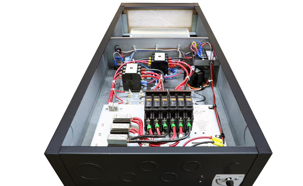
- Transformer: Each unit is equipped with a heavy duty low voltage (24 Volt) transformer for the thermostat control circuit.
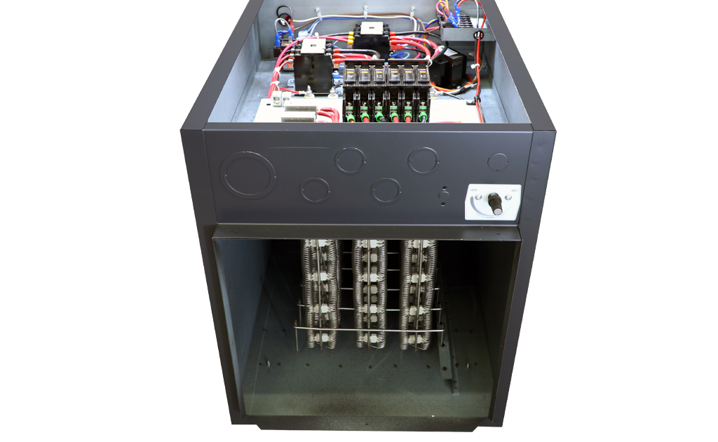
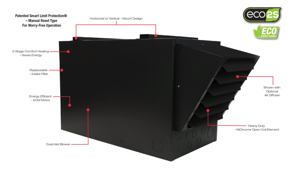
- Heating Elements: Quick heating, long life Ni-Chrome elements are sized to provide proper watt density for maximum heat dissipation by fan-forced air convection currents.
- 2-Stage Heating: 2-stage energy-saving heat output (-2S Models Only) when paired with a 2-stage 24V thermostat (purchased separately).
- Terminal Block: For single strike field wiring.
- Low Voltage Terminal Block: For 24 Volt control.
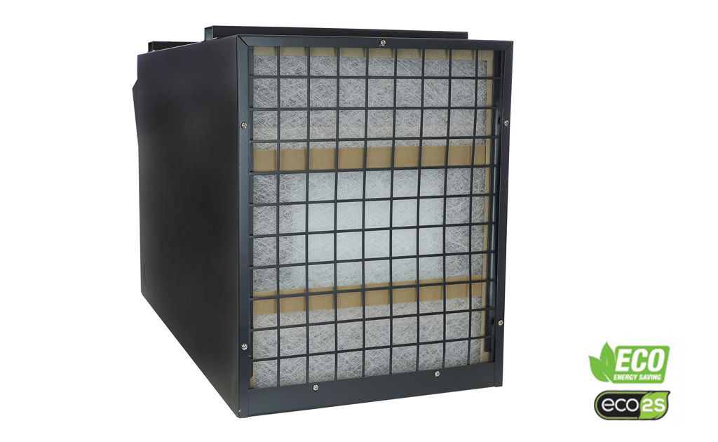
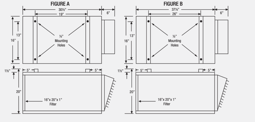
- Air Filter: Convenient access for replacement of standard 16” x 20” x 1” filter.
- Motor: Energy Saving, Long life, thermally protected, permanently lubricated, direct drive ECM motor (no belts to adjust or slip). This low noise, 5 speed motor is designated for use with air conditioning capability as well as heating. Very quiet operating. 60 second fan delay.
- Overcurrent Protection: 208 & 240 volt KFUH Endura Pro models have 60 amp circuit breakers with single strike terminal block. 480 volt models have single
strike terminal block. Units over 48 amps have 60 amp fusing. - Limit Control: Integral automatic high temperature limit control in each heating element bank prevents the delivery of air at unsafe temperatures. 20-35 kW use a manual reset limit control to completely shut the unit heater off should over temperature occur.
- Fan Relay: Heavy duty fan relay standard with summer fan operation.
- Diffuser: Various styles available and must be ordered separately.
- Approvals: cULus Certified for US & Canada


